Choosing the right cable cross section: current, length and voltage drop
Too thin and the cable heats up and loses voltage, too thick and it costs weight, space and money. Which quantities determine the right cross section, and why the voltage drop is often the deciding factor in on board power systems.
Two criteria: heating and voltage drop
The cross section of a cable has to meet two conditions. First, the cable must not heat up beyond the permissible limit at the operating current. This is described by the current carrying capacity, which depends on the cable type, the ambient temperature, the installation method and the bundling.
Second, the voltage drop along the cable must not become so large that the load receives too little voltage. In 12 and 24 volt on board power systems with long cables in particular, the voltage drop is often the stricter criterion.
Calculating the voltage drop
For direct current the following approximation applies: voltage drop ΔU = 2 · L · I · ρ / A. Here L is the single cable length in metres (the factor 2 accounts for the outgoing and the return conductor), I is the current in amperes, A is the cross section in mm² and ρ is the resistivity of copper, in practice around 0.0178 Ω·mm²/m at 20 °C.
Rearranged for the cross section: A = 2 · L · I · ρ / ΔU. If the current returns through the vehicle chassis, the factor 2 no longer applies to the cable; the contact resistance to the chassis then has to be added. At higher temperatures the resistance of copper rises and the voltage drop becomes larger.
Worked example
A work light drawing 10 A at 12 V is connected through 6 m of cable, with an outgoing and a return conductor. The permissible voltage drop is set at 3 %, that is 0.36 V. This gives A = 2 · 6 m · 10 A · 0.0178 Ω·mm²/m / 0.36 V ≈ 5.9 mm². The next larger standard cross section is chosen, in this case 6 mm².
With 2.5 mm² the voltage drop would be around 0.85 V, roughly 7 %. The work light would be noticeably dimmer. Which voltage drop is permissible is defined by the manufacturer of the load or by the customer specification.
Further influences
- Ambient temperature and proximity to heat sources
- Bundling: many cables running together heat each other up
- Cable type and insulation material with its permissible temperature
- Short term currents, for example the starting currents of motors
- Fusing: fuse and cross section have to match
- Contact and crimp: the contact has to be approved for the cross section
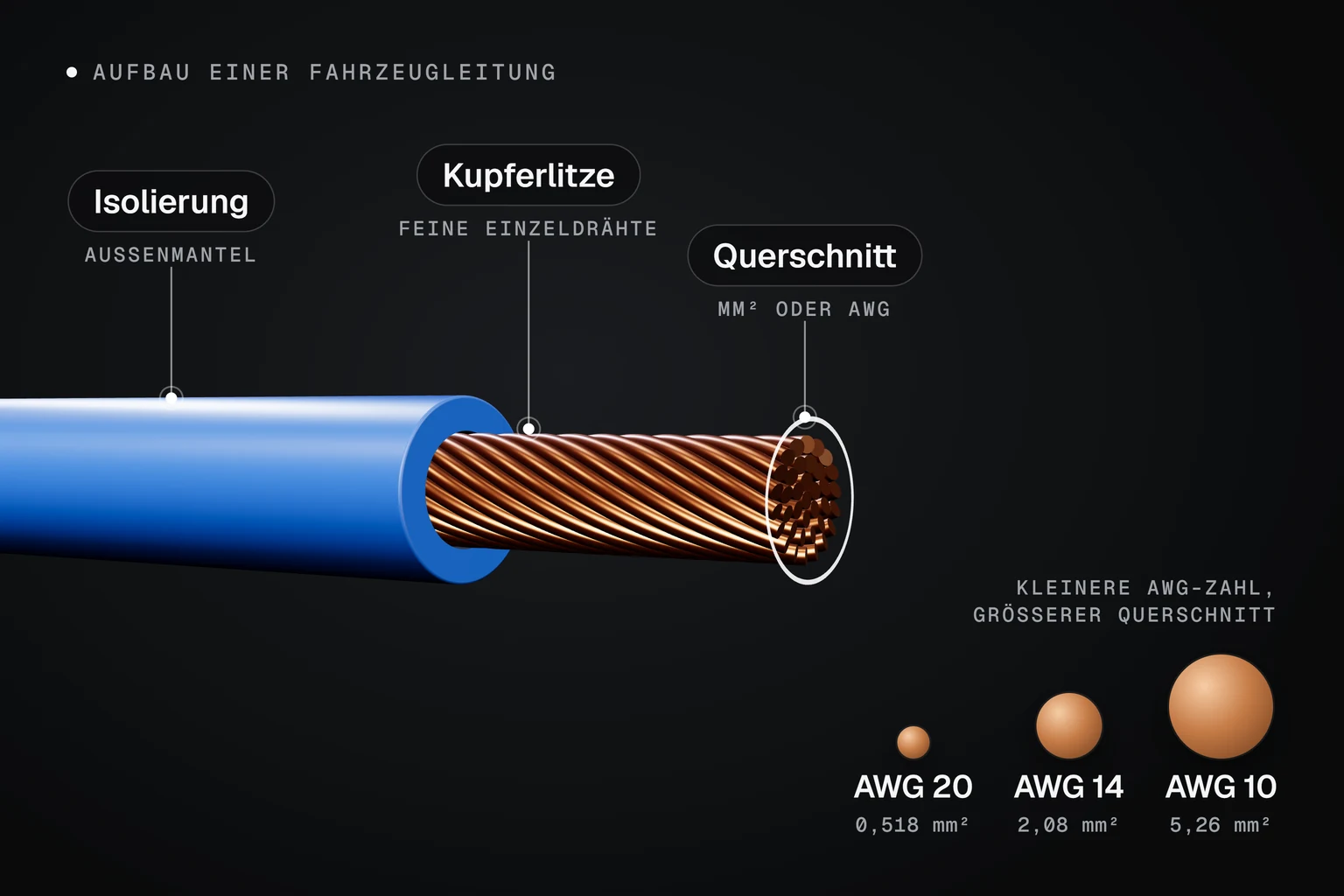
Conversions between AWG and mm² are listed in the AWG table. If you do not want to handle the sizing yourself, our design office will do it for you.